Electrical
String it with the losses in. Draw it from the same model.
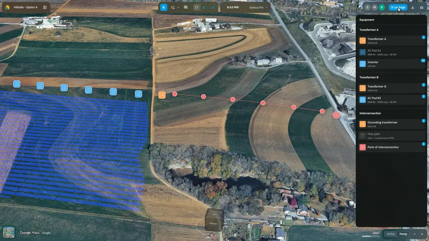
DC stringing with wire losses, AC equipment placement, a bill of materials and a single-line diagram from the modules to the grid, all off the model that produced the layout.
Trusted by leaders in solar development










What the electrical work gets back
A yield that reflects the wiring
Stringing includes wire losses, so the production figure moves when the conductor run does rather than carrying a flat derate.
Quantities that match the drawing
Equipment is placed on the site plan and the bill of materials comes off the same model, so the estimate is not a reconstruction of the design.
A one-line you mark up, not redraw
The package exports as a PDF plus one DXF per page, so a reviewer edits geometry instead of a flat sheet.
If the electrical design is yours
Your arithmetic is where an optimistic layout gets corrected, and your drawing is the one somebody reviews.
What Solesca takes off the list
- The flat derate
- When stringing lives in a separate tool, losses get applied as a number somebody chose once and nobody has revisited.
- Stringing
- Monday’s list, Tuesday’s drawing
- A materials list assembled before the last revision is where most electrical rework starts.
- Equipment and materials
- The scope line found mid-project
- Knowing which studies stay with specialist tools is worth more before a project than during one.
- Stamp and scope
Stringing
Put the wire losses into the yield
DC stringing in Solesca includes wire losses, so the yield reflects the wiring you intend to install rather than an idealised array.
- Wire losses calculated in the model, turning an assumption back into a calculation
- Unlimited DNV SolarFarmer simulation on the Engineering License
- Everything in the Design License included, so the layout and the stringing are one model
Equipment and materials
Price the equipment that is on the drawing
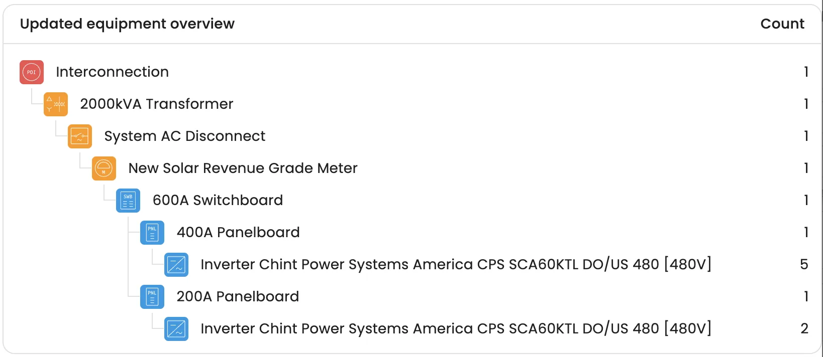
AC equipment is positioned on the site plan, and the engineering-grade bill of materials comes off the same model.
- Every piece of AC equipment in the design listed with its count
- Quantities in the estimate are the quantities in the design
- A revision to the drawing is a revision to the materials list, not a second job
Interconnection drawings
Take the single-line diagram as geometry
A three-page package drawn from the model: a site plan, a single-line diagram from the modules to the utility grid, and an equipment settings page.
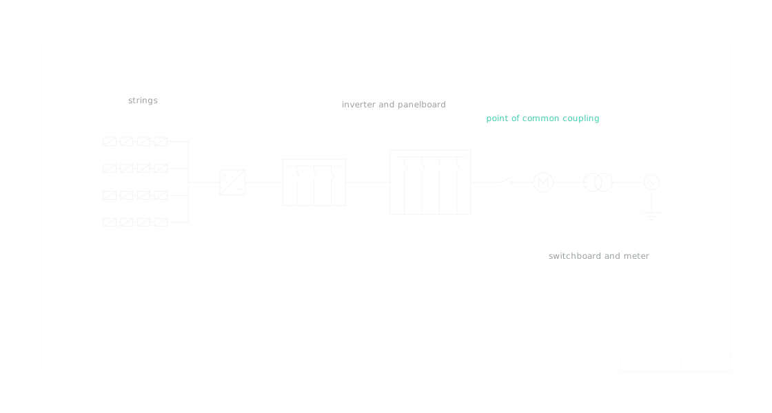
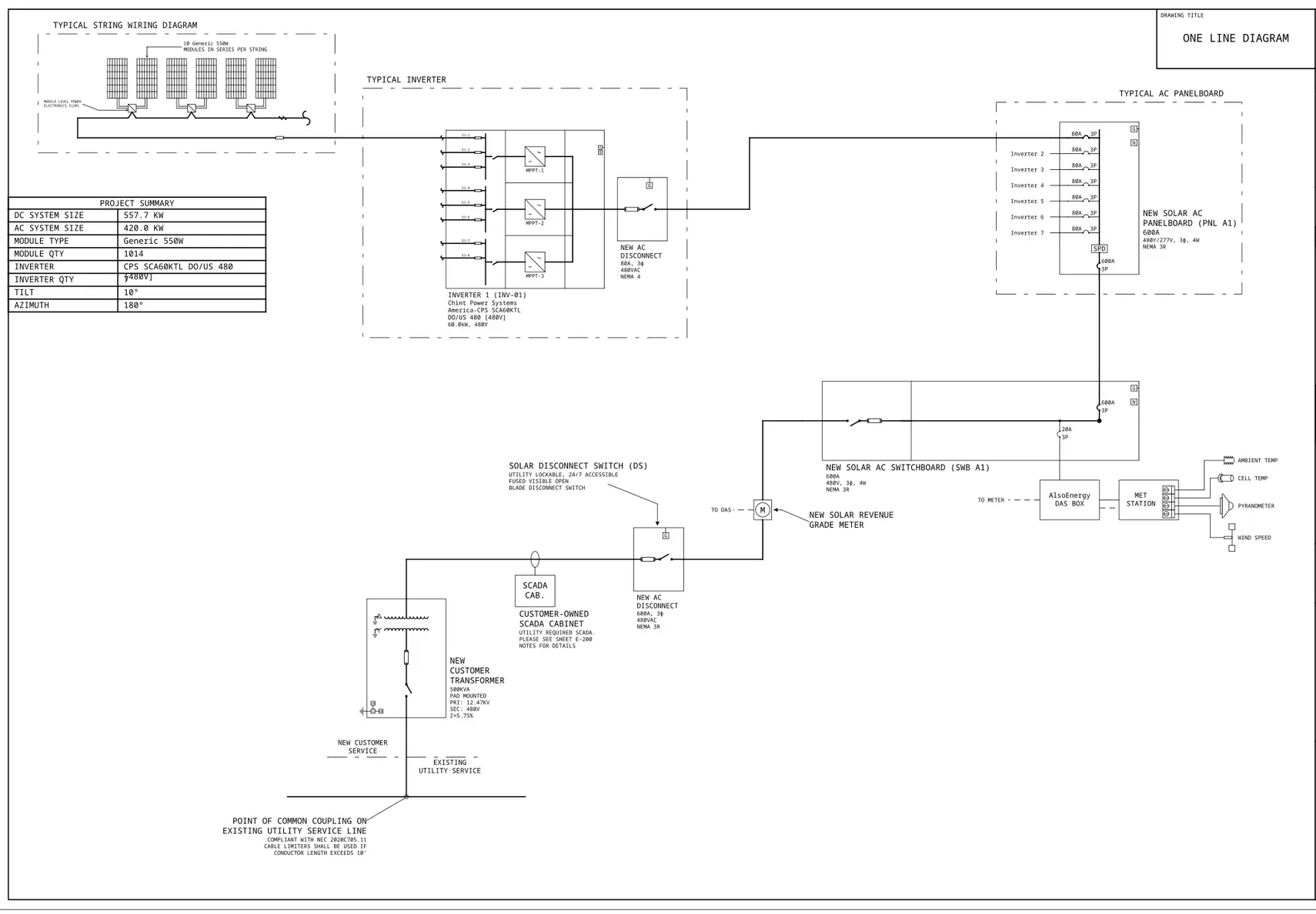
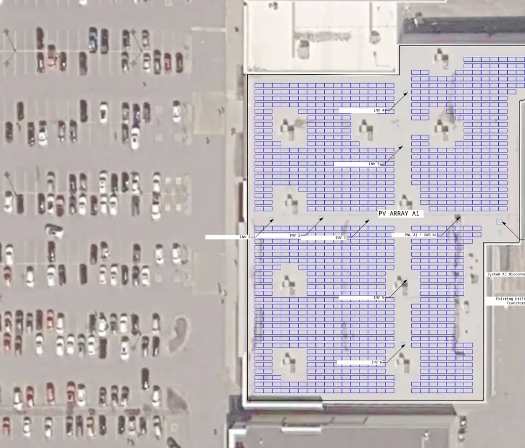
The single-line diagram, drawn from the model from the modules to the utility grid, with a detail of the site plan in front of it.
- Site plan with modules, placed equipment, parcel boundaries and roads on satellite imagery
- Equipment settings page with the equipment list, inverter settings, relay settings and notes
- Exports as a PDF plus a DXF folder with the images and one DXF file per page
Stamp and scope
Know who signs it and where the scope ends
Solesca produces the drawings and does not stamp them. A licensed PE partner stamps the package, billed at market rate through SOL Credits.
The package
Stampable drawings for systems up to three transformers, typically around 15 MW; larger systems export for reference only
Plan sets are an add-on to the Engineering License, licensed once for the organization
Stays with specialist tools
No protection coordination, arc-flash or short-circuit studies. Those stay with specialist tools
Who already runs it this way
Before Solesca, our sales and engineering teams were misaligned on system sizes by up to 15-50%. Now, everyone is on the same page, which drastically reduces rework.
How it runs, from layout to interconnection drawings
- 01
String
String the array on the layout, with wire losses carried into the yield.
- 02
Place
Position the AC equipment on the site plan.
- 03
Price
Take the bill of materials off the same model.
- 04
Draw
Generate the site plan, single-line diagram and settings page, and export PDF and DXF.
The detail, if you want it.
The long answers, for the reader who wants them.
Why do wire losses belong in the design tool?
Because a production figure that ignores the conductor run is a figure that gets revised later, in front of a customer. DC stringing in Solesca includes wire losses, so the yield reflects the wiring you intend to install rather than an idealised array.
When stringing lives in a separate tool, the losses get applied as a flat derate — a number somebody chose once and nobody has revisited. Doing it in the model turns an assumption back into a calculation.
What does the single-line diagram show?
The run from the modules through to the utility grid, drawn from the same model that produced the layout. It ships as part of a three-page package with the site plan and an equipment settings page carrying the equipment list, inverter settings, relay settings and notes.
It exports as a PDF plus a DXF folder with the images and one DXF file per page, so a reviewer marks up editable geometry rather than redrawing a flat sheet. The configurations the diagram covers are listed on the plan sets page.
Does the equipment on the drawing match the equipment priced?
It should, and that is the argument for doing placement and the bill of materials in one place. AC equipment is positioned on the site plan, and the engineering-grade bill of materials comes off the same model, so the quantities in the estimate are the quantities in the design rather than a reconstruction of it.
This is the seam where most electrical rework starts: a drawing revised on Tuesday and a materials list assembled on Monday. One model removes the seam rather than managing it.
Who signs it, and how big can it get?
A licensed PE partner stamps the package, billed at market rate through SOL Credits — Solesca produces the drawings and does not stamp them. If your own firm holds the stamp, that route simply goes unused.
Stampable drawings export for systems up to three transformers, typically around 15 MW. Larger systems still export, carrying a disclaimer that marks them for reference only. Plan sets are an add-on to the Engineering License, licensed once for the organization rather than per package.
What electrical work does Solesca not do?
It does not run protection coordination, arc-flash or short-circuit studies. Solesca covers stringing, equipment placement, the bill of materials and the interconnection drawings; the studies that sit beyond those stay with the specialist tools and the engineer who signs them.
That line is worth knowing before a project rather than during one. Everything named on this page is scope Solesca carries end to end.
Does Solesca stringing account for wire losses?
Yes. DC stringing includes wire losses, so the yield figure reflects the wiring you will install.
What is in the interconnection package?
Three pages: a site plan showing modules, placed equipment, parcel boundaries and roads on satellite imagery; a single-line diagram from the modules to the utility grid; and an equipment settings page with the equipment list, inverter settings, relay settings and notes.
Do I need the Engineering License for a single-line diagram?
Yes. Plan sets and single-line diagrams are an add-on to the Engineering License, licensed per organization; the Design License cannot take it. Stamping is billed at market rate through SOL Credits.
Bring a job where the derate was a guess
String a real array, let the wire losses land in the yield, and see how far the number moves from the flat derate you have been carrying. Thirty minutes with our U.S.-based engineering team.